Thursday, 15 February 2018

Wemos Matrix LED Shield, Wemos Full Color RGB Shield (WS2812B), 4-Digit 7-segments LED Display Tube

In this post I will introduce 3 led based displays.

Matrix led shield for Wemos Mini D1

Hardware setup

This shield uses two data pins
D5 = CLK
D7 = DIN

It has 8x8=64 red led

From code you can light any led with x and y coordinates, and set brightness with 8 steps.

Software setup

You will need library from Wemos. That is not in Arduino library manager so you have to download it from Git
https://github.com/wemos/WEMOS_Matrix_LED_Shield_Arduino_Library
For information on installing libraries, see: http://www.arduino.cc/en/Guide/Libraries

Code example

In this example leds go out and with every line they go brighter.

Links

https://wiki.wemos.cc/products:d1_mini_shields:matrix_led_shield

RGB led Shield for Wemos Mini D1

With this shield you can generate  16777216 different colors.

Hardware setup

It needs 5v and D2 as data line.

Software setup

You need to install Neopixel library
https://github.com/adafruit/Adafruit_NeoPixel
or from Library manager
For information on installing libraries, see: http://www.arduino.cc/en/Guide/Libraries

Code example

Links

4-Digit 7-segments LED Display Tube

There are different versions where is Clock dots, or decimal dots.
In this example i have clock version.

Hardware setup

This Module uses two data pins
D6 = CLK
D5 = DIO

Works both 3.3V and 5.0V


Software setup

There might be several libraries that works with this module, but i have used this simple library
https://github.com/avishorp/TM1637
For information on installing libraries, see: http://www.arduino.cc/en/Guide/Libraries

Code example

In this example:
- Show number with and without leading zeros
- Show Time
- Show brightness setting (8 levels)
- Show setting individual segments, and all possible combinations (128 pcs.).

Links

Monday, 12 February 2018

128X64 0.96" OLED Dsiplay (Monochrome)

Interface

I have chosen board with I2C interface because it takes only 2 data lines.
You can see the difference from number of pins I2C has 4 and SPI has 7
So what is advantages for SPI, because it has more data lines?
It should be faster, but if you are not going to show videos, it's not worth it (Personal opinion)


Price <3$
3.3V Data Lines
Driver: SSD1306
Interface IIC(I2C)

You can get one from here.

Some models might be 5V compatible, but you have to check specs for that. I have run mine with 3.3V

From this display I have seen two variations, one color, and two colors, where top part of screen is different color. Down side on this is that there is noticeable black line between colors.

On my board there where printed wrong I2C address, but you can use this I2C scanner to detect your address.
https://playground.arduino.cc/Main/I2cScanner

Hardware setup

VCC -> 3.3V
GRN -> GND
SDA -> D2 (Wemos D1 Mini)
SCL -> D1 (Wemos D1 Mini)

Software setup


For this display you need two libraries.


You need to check from...\Documents\Arduino\libraries\Adafruit_SSD1306\Adafruit_SSD1306.h

Change your I2C address and check that  SSD1306_128_64 Size is not commented.


Code Example

- -

Links

You can create bitmaps with this tool
http://javl.github.io/image2cpp/

Rest of the graphics commands can be found from this page.
https://learn.adafruit.com/adafruit-gfx-graphics-library/graphics-primitives

Remember to check examples that came with adafruit-graphics library!

Adafruit demo


Cheap display keyboard TM1638

TM1638 led&key

With this module you will get buttons and numeric display in one package.
8 led, 8 7-segment numbers and 8 buttons using only 3 data lines and less than 2$.

You can get one from Here.

Hardware setup

For demo you have to connect following pins
DIO GPIO4 (Wemos D2)
CLK GPIO14 (Wemos D5)
STB GPIO12 (Wemos D6)
VCC +5v
GND GND

Software setup


There are few Arduino libraries that you can use.
This library has most starts in Github, and I will show example about it.
https://github.com/rjbatista/tm1638-library
For information on installing libraries, see: http://www.arduino.cc/en/Guide/Libraries

Library has one bug open, that you should take in to account.
setDisplayToDecNumber should display "0"

If you get error like:

TM16XX.cpp:44:66: error: no matching function for call to 'min(int, byte&)'

You need to add these lines to beginning of file c:\Users\myname\Documents\Arduino\libraries\tm1638-library-master\TM16XX.h
#define max(a,b) ((a)>(b)?(a):(b))
#define min(a,b) ((a)<(b)?(a):(b))
More info at: https://github.com/esp8266/Arduino/issues/398
Path to Arduino libraries can be something else, you can see your path, from menu File -> Preferences -> Sketchbook location

Demo

First is example how you can define place of dot.
Next is shown how this library shows alphabets. I think this library and display is not good for showing text.
In the end I will show how to check what buttons are pressed and how to light led on top of module.


Saturday, 10 February 2018

Powering ESP-8266 with Battery (Deep sleep)

Deep Sleep

In this mode ESP has only Realtime clock running, and after set time, it will set reset pin to low through GPIO16 pin, then ESP resets and wakes up.

To be able to wake up ESP you need to connect reset and GPIO16 pins together.

Remember that ESP always start program execution from the beginning after waking up from deep sleep.

Note that while these pins are connected you might not be able to flash new sketch. You can try to flash by resetting ESP at just a right moment. But better way is to but switch between RST and GPIO16 pin, so you can disable deep sleep functionally temporary.


Waking ESP from external source


Also if you need to wake ESP from external source like door switch you can put it between ground and RST pin. I will show this with my todays example "Mailbox monitor"


Power consumption


First of all, you should choose ESP board with no extra features like one that don’t have power led on all the time.
I'm using Wemos D1 mini and have measured that it uses only 60 µA in deep sleep mode.
With this consumption you can run ESP for months with battery.

Of course, depends what you do with it between sleeps. I have tested application that measures battery voltage every half hours and sends it to internet, and it has been running with AAA batteries for one month now and has dropped only 0.5 volts.

The lowest power consumption is achieved by feeding the ESP directly from the 5V line, in my test it took 3.5 mA on deep sleep if powered via USB connector, and 0.060 mA from 5V line.

Specs for Wemos D1 mini regulator(RT9013) says you can power up to 5,5 volts(Absolute Maximum 6.0v)

3 x AA battery = (Empty) 3,3V - (Full) ~4,8V
4 x AA battery = (Empty) 4.4V – (Full) ~6,4 V
4 x NiMh AA battery = 4.0V - (Full) ~6.0 V

Using 3 Batteries is fine by specs, but you can’t power 5v sensors with that, and on my test ESP was shut down at 3.5V so you can’t fully utilize full battery capacity.

Using 4 Batteries is over spec, and can fry your ESP.
So best would be using 4 batteries that are not brand new, and together measures about 5.6 volts.
Or if you have 1.2V NiMh batteries, they would be ideal.

In one of my projects I’m using 4 x AA batteries and have been lucky that everything works fine.
Also on project that don’t use 5V sensors I have used 3 x AA batteries.

I will cover usage of Li-Po/Li-Ion batteries in another post.

Example project - Sleep until someone opens mail box

When RST & GND is connected esp will reset, and when these are disconnected ESP will wake up.

Thursday, 8 February 2018

ESP Web server implementing guest book

Used technologies 

In this post, I will show how the ESP-8266 works as a Web server and DNS server over a WiFi access point.

It uses ESP's internal SPIFFS file system to store static files and user comments on web servers.

For this project you don't need any extra hardware, so plain ESP board is enough. I used Wemos D1 mini. Like Here

To upload static JavaScript files and libraries to the ESP file system, you need to install a special tool for Arduino IDE.You can get it from Here. ( Arduino ESP8266 filesystem uploader )


On client side project uses JQuery, Bootstrap, and Vue.js
https://jquery.com/
https://getbootstrap.com/
https://vuejs.org/

Because this is not JavaScript blog, I won't go through the client side so much.

Whole project can be found from my git HERE

Setup


Copy files from GIT or clone it to your hard disk.
"Data" folder has files that filesystem uploader will copy to ESP, this folder has to be in same folder as "Vieraskirja1.ino".

Install "Arduino ESP8266 filesystem uploader" if you do not yet have it. Remember to restart Arduino IDE after installing it.

Server code

- -

Client code

Client code is in one file, to enable easy OTA (over-the-air) updates to client code.
Used JavaScript libraries are minified and gzipped to save bandwidth.
ESP is not so powerful as a normal web server, and Wifi APN allows only 4 user to connect at the same time.
--

Using GuestBook

When you have uploaded codes to ESP, it's time to fire it up.

There should now be new Wifi Access point called "MyIoT", connect to it.

You may see this kind of notification, saying "Wifi is not connceted to internet, should we keep connection" (Sorry, picture is in Finnish)
Answer yes to it, so connection is not closed after while.
Then go with your browser to "www.iot.com", do not forget www from front of it!
Now you should be able to see guest book, and be able to send messages.

OTA update

This is only for advanced users, and I might do separate post about this.

Update is not done as good as it could, it's only rest service where you need to send new file. You can use chrome extension called POSTMAN.


Wednesday, 7 February 2018

Setting up environment for esp8266 using Arduino IDE


Drivers

For my Wemos D1 Mini board I didn't have to install any additional drivers, those that came with Arduino IDE worked directly.

Drivers for your board:
With esp there is different USB to UART Bridges on different board manuafactures.
CP2102
CH340G or CH340

I have found that they both work ok, but some say that CP2102 is better.
You can see difference if you check chip near usb port.
CP2102 chip is square and CH340G is just rectangle.

You can read more and get drivers from
Link

If you don't yet own ESP you can check this out and get started: Link to eBay

Installing Arduino IDE


Get and install it from this download link.
If you already have it check that you have at least version 1.6.4

Installing ESP library to Arduino IDE


On Arduino IDE go to 'file' menu and select 'preferences'.
From there fill in the 'Additional board managers URL' this url:  http://arduino.esp8266.com/stable/package_esp8266com_index.json

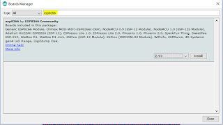
Go to 'Tools' and 'Board Manager..'

From there search "esp8266", and install it.

Now you have new boards in "board" menu.
In my case i select Wemos D1 mini.

Next you have to select correct COM port, and you can also select CPU Frequency and Flash Size, i will talk about these more on following posts. Defaults for these are fine for now.

There is now also new examples, and you should start with basic Blink sketch and see that you can compile and upload it to your board.


Welcome words

ΩHi!


This blog is documenting my findings with IoT devices, helping all who have had the same problems as I have.
I mostly use esp8622 and Arduino boards, but also raspberry pi.

To be precise, I use

  • Wemos mini D1 esp boards.
  • Arduino Uno and Arduino Nano boards.
  • Raspberry pi Zero.


My blog posts will start with introducing several cheap china sensors that you can plug in to esp and Arduino.

Where did i came up with blog name 10 kΩ
It's common pull-up resistor value, when you are working with Arduino. There is always a shortage of them.